Cnuas Datacentre Simulation

AI/HPC Hyperscale Data Center Simulation

Cnuas models a hyperscale AI campus as one artefact, from the silicon up to the site. The rack that runs the workload is emulated in software, and the campus that would house it is generated as an OpenUSD stage that opens in NVIDIA Isaac Sim, usdview, Blender or any other USD capable tool.

The two halves are joined. Site electrical load is computed from the same racks the emulator runs, so a change in compute load moves the number on the grid connection. Nothing here is driven by a synthetic trace.

Read the documentation Facility Twin design Facility datasheet (PDF) ↓
A walk through the generated campus, the buildings, the data halls, and the two racks Cnuas emulates. Every rectangle in the film is drawn from the output of plan.plan_campus(), so it is the same geometry the OpenUSD exporter writes to the stage. (MP4, 2:14, with narration.)
The campus

From One Rack to a 291 MW Campus

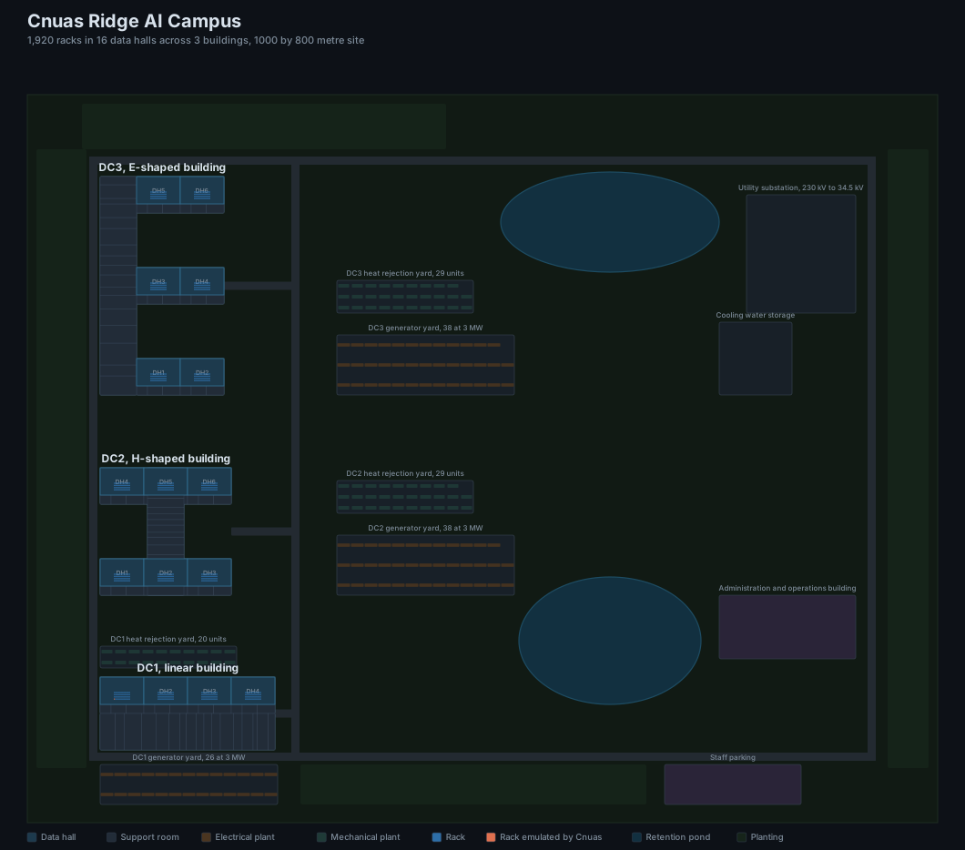
The reference campus, default_campus(), is a 1,000 by 800 metre site holding three datacentre buildings, sixteen data halls, 1,920 racks and a 291 MW facility load.

Plan of the Cnuas Ridge AI Campus: three datacentre buildings, generator and heat rejection yards, a utility substation, retention ponds and planted screening across a 1000 by 800 metre site.
The reference campus, generated from the model. Every rectangle is read from the same planner the USD exporter consumes, so the drawing and the stage cannot disagree.
1,920
Racks
253.2 MW
IT Load
291.2 MW
Grid Connection
1.15
Design PUE

The shape is the strategy

Building forms are not styling. In an H or an E the central spine carries the electrical and mechanical plant while the data halls occupy the limbs, so every busway run and every pipe header stays short. The shape is the distribution strategy made visible.

BuildingShapeData hallsRacks
DC1I, linear4480
DC2H6720
DC3E6720

A site that a fire appliance can reach

Buildings sit west of the north to south service spine. Plant yards, the utility substation, cooling water storage, the administration building and parking sit east of it, which keeps the route from the loading dock to any hall short and gives a fire appliance a way to every face of every building.

Two retention ponds and four planted screening belts complete the site. The ponds are amenity, and they are also stormwater and thermal infrastructure, which is why real campuses have them.

Inside a data hall

Emitted Rack by Rack

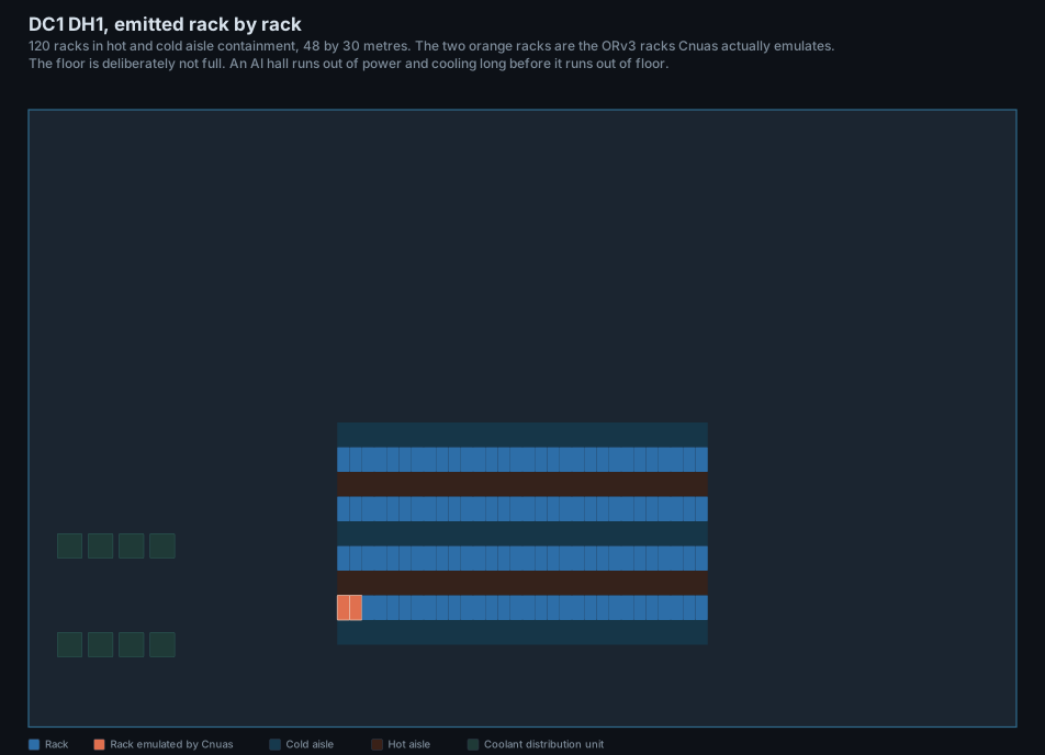
Fifteen of the sixteen halls are emitted as named volumes carrying a rack count and a load. One hall, DH1 in DC1, is emitted rack by rack.

Rack level plan of data hall DH1 in building DC1, showing rows of racks with the two racks Cnuas emulates highlighted.
Data hall DH1, emitted rack by rack. The two racks in orange are the ORv3 racks the emulator runs.

Driven by the emulator, not a spreadsheet

The two emulated racks carry a telemetry attribute on their USD prim:

cnuas:telemetry:source = "modbus-rtu://127.0.0.1:3485/0xc0"

That address is a real power supply on the emulated ORv3 power shelf. Reading PSU_Output_Voltage and PSU_Output_Current from it gives a measured wattage that is written back onto cnuas:power:drawKw, which is how the campus is driven by the emulator rather than by a spreadsheet.

A hall is more than its floor

The empty area in the plan is not slack. It goes to coolant distribution and to the next phase, because a liquid cooled hall is limited by power and heat rejection rather than by square metres.

Each building carries the full TIA-942-B room programme, from the Entrance Room and Meet-Me Room through the Main Distribution Area to the data hall, with a Horizontal Distribution Area, coolant distribution room and fan wall gallery per hall, plus the medium voltage switchgear, transformer vault, paralleling switchgear, battery, pump and water treatment rooms that make a building run.

The rack Cnuas emulates

Two ORv3 Racks on One Workstation

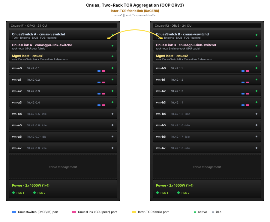
Two racks on the Open Compute Project Open Rack v3, each carrying two 1OU top of rack switches, a management host, and eight 2OU blades. Every blade is a guest with an emulated RDMA adapter and one or more emulated accelerators. The whole deployment runs on one workstation.

Front view of the two rack Cnuas reference deployment on Open Rack v3, showing top of rack switches, a management host and eight blades per rack.
The numbers

Computed, Not Quoted

Change the rack count or the rack type and every figure below moves, including the number of generators.

QuantityValue
Racks1,920
IT load253.2 MW
Design PUE1.15
Facility overhead38.0 MW
Grid connection291.2 MW
Heat to reject253.2 MW
White space23,040 m2
Power density11.0 kW/m2
Standby generators99 at 3 MW
Generate it yourself

Every Figure on This Page Is Reproducible

The campus, the room programme and the power roll-up are produced by the same command line tool that writes the OpenUSD stage.

cnuas-facility
pip3 install -e facility

cnuas-facility power                     # the power roll-up, no USD needed
cnuas-facility rooms                     # the room programme, per building
cnuas-facility build --out campus.usda   # the OpenUSD stage

cnuas-facility live --duration 60        # drive the stage from the power shelf

Open campus.usda in NVIDIA Isaac Sim, usdview, Blender, or any other USD capable tool. The plans on this page are regenerated with python3 facility/scripts/render_plan.py.

Datacentre Simulation → Facility Twin design OCP Rack Management Facility datasheet PDF ↓