Cnuas System Topology¶
1. Overview¶
The Cnuas Virtual AI HPC Infrastructure is a layered, 100% software-emulated data center stack. Five components cooperate at three planes:
| Plane | Component | Role |
|---|---|---|
| Host userspace daemons | cnuas-vswitchd (CnuasSwitch) |
RoCE/IB fabric switch |
cnuasgpu-link-switchd (CnuasLink) |
GPU-to-GPU interconnect (NVSwitch-equivalent) | |
| QEMU device models | cnuas_vnic |
Virtual RoCE-IB NIC PCIe device (Gen5 x16) |
cnuasgpu |
Virtual GPU PCIe device (Gen5 x16) | |
| Guest | Kernel modules + libcnuas-rdmav34.so provider + libcnuasrt.so runtime |
Verbs and runtime exposed to applications |
Two independent fabrics carry distinct kinds of traffic:
- The CnuasSwitch fabric carries every Ethernet frame including
RoCEv2 (UDP/4791) RDMA traffic. This is the data network and
is what
ibv_rc_pingpong/perftest/ NCCL's IB transport flow over. - The CnuasLink fabric is independent. It carries only CnuasGPU ↔ CnuasGPU peer traffic, the equivalent of NVIDIA NVLink. A VM with a CnuasGPU but no CnuasNIC can still do GPU-to-GPU; a VM with CnuasNIC but no CnuasGPU never touches CnuasLink.
A real VM typically has both
(-device cnuas-vnic ... -device cnuasgpu ...) and therefore wires
into both daemons via separate UNIX-domain sockets.
2. Physical Rack Reference (OCP Open Rack v3)¶
Cnuas's physical-equivalent model is the Open Compute Project Open Rack v3 (ORv3), the 2023+ revision used by every major hyperscaler for AI/HPC builds (Meta, Microsoft Azure Maia, Google's TPU pods, NVIDIA HGX/B200 reference designs). ORv3 is not just a deeper EIA-310 rack; it's a different rack with different mechanical, electrical, and serviceability properties:
| ORv3 property | Value | Why it matters for Cnuas |
|---|---|---|
| Rack-unit height (OU) | 48 mm (vs 44.5 mm for 19″ U) | All our rack diagrams are sized in OU |
| Equipment bay width | 21″ (537 mm), 20 % wider than 19″ | Gives room for 8x GPU sleds + dual-NIC headers |
| Power | 48 V DC busbars at the rear, fed by a power shelf | Hot-pluggable PSUs; no per-server AC inlets |
| Servicing | Front-only; cables and connectors on the cold aisle | Switch + GPU + compute all share the cold-aisle service model |
| Modular zones | power / equipment / cable | Maps 1:1 to our TOR-row / blade-rows / cable-bay layout |
Why ORv3 and not ORv2? ORv2 (2014) targeted general-purpose cloud workloads; ORv3 (2023) is the rack the AI buildout was designed around, wider 21″ bays, denser busbars, and explicit support for top-of-rack accelerator-optimised switches like the ones CnuasSwitch + CnuasLink emulate. An ORv2-style 19″ rack would not fit the dual-fabric (RoCE TOR + GPU peer switch) header we ship one rack-unit apart in every Cnuas rack.
2.1 Component-to-ORv3 Slot Mapping¶
| ORv3 slot (top-down) | Cnuas component | OU height | Function |
|---|---|---|---|
| 1OU | cnuas-vswitchd (CnuasSwitch TOR) |
1 | RoCEv2 + InfiniBand fabric, 10 ports, DCB |
| 1OU | cnuasgpu-link-switchd (CnuasLink spine) |
1 | GPU peer fabric, 8 ports, NVSwitch-equivalent |
| 1OU | Management host | 1 | Bare-metal Ubuntu; runs the two daemons + real GPU |
| 8x 2OU | VM "blades" (QEMU guests) | 16 | Each carries CnuasNIC + CnuasGPU + the full guest stack |
| 4OU | Cable management | 4 | UDS files in /var/run/cnuas/ and /var/run/cnuaslink/ |
| 2OU | Power shelf (1+1 redundant PSUs) | 2 | 48 V DC to rear busbar |
| Total | 24 OU | Half-height ORv3 rack; ORv3 racks ship in 41 OU and 44 OU heights |
In the emulator the "U-height" is purely visual, components are
processes and .qcow2 images, not metal, but the mapping makes
it easy to point at a real ORv3 photo and explain what each
Cnuas process would be if it were physical.
2.2 Single Rack (front view)¶
This is the basic deployment: one rack, two switches at the top (CnuasSwitch + CnuasLink), one management host, eight VM slots, power at the bottom.
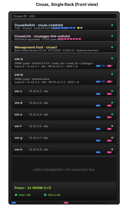
Green LED = active, grey LED = idle. Blue port stubs are the
RoCE/IB fabric; pink port stubs are the CnuasLink GPU fabric. Every
"cable" you see is a SOCK_SEQPACKET UNIX-domain socket on the
host, the emulator preserves every interface and connector you'd
find in a real ORv3 rack, just transported over UDS instead of
copper/fibre.
2.3 Two Racks Aggregated¶
Scale-out: two ORv3 racks adjacent in a hot-aisle / cold-aisle row, peered via a single yellow inter-TOR cable. CnuasLink stays rack-local (NVSwitch domains do not span racks); cross-rack GPU traffic falls back to RoCEv2 through the two TORs, the same path NCCL would take in a real cluster.
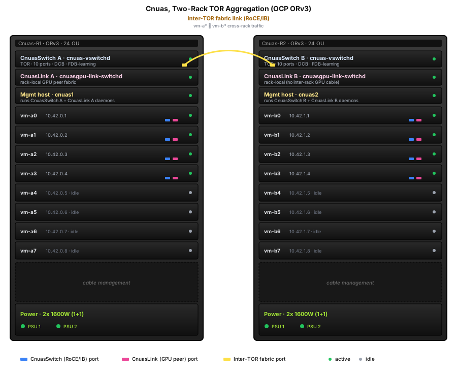
The wire-level mechanics of the inter-TOR link (FDB learning via gratuitous ARP, IB Subnet-Administration traffic, etc.) are covered in Cnuas Virtual Switch Design §1.2.
2.4 Logical View (same topology, no chassis)¶
If you want to look past the rack and just see who talks to whom, this is the same two-rack layout as a labelled flowchart.
Note the dotted lines: CnuasLink connections never leave the rack.
3. Host-Level Topology¶
This is the canonical two-VM development layout used by the
tests/test_rocev2_e2e.py gate.
Legend. Solid lines (===) carry RoCE/IB traffic over the
CnuasSwitch fabric. Dotted lines (-.->) carry GPU-to-GPU traffic
over the CnuasLink fabric. Each connection is a SOCK_SEQPACKET UDS
between the QEMU device backend and the corresponding switch
daemon.
4. Per-VM Internal Topology¶
Inside a single VM, the kernel and userspace stack stratifies as follows. The arrows show call direction, not data direction (RDMA data motion is reflected by what each verb does, not by the ABI boundary).
* NCCL runs only on the host today, not in VMs, the guests
have no CUDA driver and no CUDA-capable PCI device. Pulling NCCL
into the guest is tracked by the cnuasnic-nccl L2/L3 backlog and
requires either GPU passthrough into the VM or our patched kernel
loaded on the bare-metal host.
4.1 ABI Boundaries¶
| Boundary | Direction | Mechanism |
|---|---|---|
| App ↔ libibverbs | function calls | C ABI, stock rdma-core |
| libibverbs ↔ libcnuas provider | function-pointer table (verbs_context_ops) |
resolved at dlopen time when driver_id == RDMA_DRIVER_CNUAS |
| libibverbs ↔ kernel | ioctl on /dev/infiniband/uverbsN |
uverbs cmd mask + UAPI structs |
kernel verbs ↔ cnuas_ib.ko |
function-pointer table (struct ib_device_ops) |
resolved at ib_register_device() |
cnuas_ib.ko ↔ cnuas_net.ko |
per-frame notifier chain + dev_queue_xmit |
RoCEv2 framing happens here |
cnuas_net.ko ↔ QEMU cnuas_vnic |
MMIO BAR + IRQ doorbell | virtio-like rings on a memory window |
QEMU cnuas_vnic ↔ CnuasSwitch |
SOCK_SEQPACKET UDS |
one connection per port |
App ↔ libcnuasrt.so |
function calls | C ABI |
libcnuasrt.so ↔ cnuasgpu.ko |
ioctl on /dev/cnuasgpu0 |
custom UAPI |
cnuasgpu.ko ↔ QEMU cnuasgpu |
MMIO BAR + IRQ | command/completion rings |
QEMU cnuasgpu ↔ CnuasLink |
SOCK_SEQPACKET UDS |
one connection per port |
5. Fabric Walks¶
5.1 RoCEv2 frame end-to-end (vm-a → vm-b)¶
This is what ibv_rc_pingpong and the e2e gate exercise.
Per-frame cost is dominated by two UDS hops and the kernel-side
ICRC compute on TX + validation on RX. Multi-packet SEND/WRITE
(>MTU) fragments into FIRST + N×MIDDLE + LAST sequences; ACKs
coalesce by setting ackreq=1 only on LAST/ONLY.
5.2 CnuasLink (GPU-to-GPU) frame walk¶
For comparison: the CnuasLink fabric uses a much smaller wire header because it's an interconnect, not a fabric, and ignores Ethernet framing entirely.
CnuasLink has no IBA framing, no ICRC, no PSN/ACK reliability, it mirrors the NVLink/NVSwitch programming model where the interconnect is assumed lossless and ordered.
6. Packaging and Deployment Topology¶
How the artifacts produced by cnuas-tools pkg build map to
where they install:
The split is deliberate:
- The switch and link daemons are host-side processes; they never ship into the VM.
- The kernel modules + provider + GPU runtime ship inside the VM image because they have to be loaded by the guest kernel.
cnuas-nccl-testsis host-only because NCCL needs real CUDA.
7. Address-space Summary¶
| Identifier | Space | Allocator | Example |
|---|---|---|---|
| Ethernet MAC | 48 bits | static, encoded in QEMU args (52:54:00:42:00:NN) |
52:54:00:42:00:01 |
| IPv4 (data) | private /24 | static at boot | 10.42.0.1, 10.42.0.2 |
| IPv4 (mgmt SSH via SLIRP) | localhost loopback | qemu user-net | localhost:2222, localhost:2223 |
| IB GID | 128 bits | derived: ::ffff:<data IPv4> |
::ffff:10.42.0.1 |
| QPN | 24 bits | per-device counter | 1..N |
| CnuasLink GPU ID | 8 bits | static, from -device cnuasgpu,gpu_id=N |
0..7 |
| CnuasSwitch port | 4 bits | static, 10-port fixed layout | 0..9 |
| CnuasLink port | 3 bits | static, 8-port fixed | 0..7 |
8. Code-to-Concept Cross-Reference¶
| Concept | Code home | Key file |
|---|---|---|
| CnuasSwitch daemon | src/cnuasswitch/switch/ |
src/main.c, src/eth_pipeline.c, src/ib_pipeline.c |
| CnuasSwitch CLI | tools/src/cnuas_tools/ |
pkg/, deploy/ |
| CnuasLink daemon | src/cnuaslink/switch/ |
cnuasgpu-link-switchd source |
| CnuasLink CLI | src/cnuaslink/cli/ |
Python, Typer + Rich |
| CnuasNIC QEMU device | qemu/hw/net/cnuas_vnic.c |
full PCIe + MMIO + UDS bridge |
| CnuasNIC kernel module | src/cnuasnic/kernel/ |
cnuas_net.c, cnuas_ib.c, cnuas_proto.h |
| CnuasNIC userspace provider | src/cnuasnic/rdma-core/cnuas.c |
the real one, not userspace/libcnuas.c |
| CnuasGPU QEMU device | qemu/hw/misc/cnuasgpu/ |
PCIe + CnuasLink endpoint |
| CnuasGPU kernel module | src/cnuasgpu/kernel/ |
cnuasgpu.c |
| CnuasGPU runtime | src/cnuasgpu/userspace/libcnuasrt/ |
libcnuasrt.so |
| VM image build | tools/src/cnuas_tools/image/ |
image build Typer command |
| Packaging | tools/src/cnuas_tools/pkg/targets/ |
one module per .deb target |
| E2E gate | tests/test_rocev2_e2e.py |
15 cases: pingpong, perftest, SRQ, atomics, UD |
| NCCL L1 gate | tests/test_nccl_link.py |
7 cases: deb build, ldd, dlopen, init banner |
9. Live Traffic Flow (animated)¶
The SVG below is animated SMIL, it loops continuously while the page is open and behaves like a silent embedded video. Two flows are shown concurrently against the same physical rack pair from §2:
- Blue, A RoCEv2 SEND from
vm-a0tovm-b0(cross-rack): the packet rises out of the VM, hits TOR A, crosses the inter-TOR cable, drops into TOR B, then lands invm-b0. - Pink, A CnuasLink
cnuasrtMemcpyPeerfromvm-a1's GPU tovm-a2's GPU (rack-local): up to CnuasLink A, back down to the peer VM. Never touches the TOR.
The diagram above is an embedded animated SVG. If you see a still
image, your browser is rendering it through the fallback <img>
tag which may suppress SMIL animation in some Chrome versions; open
the SVG directly and the blue +
pink packet dots will loop continuously.
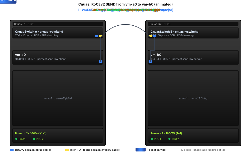
If your browser has prefers-reduced-motion set the animation
auto-disables (the SVG falls back to the static layout).
9.1 Recording a real screen-capture video¶
The animated SVG is good for documentation and is built-in to the
docs. If you want an actual MP4/WebM (e.g. to embed in a slide
deck or share standalone), capture the rendered SVG with ffmpeg:
# 1. Serve the docs locally so the SVG renders with its animations.
mkdocs serve --dev-addr 127.0.0.1:8765 &

# 2. Capture the SVG region for one full animation period (12 s = 2
#    RoCEv2 loops + 3 CnuasLink loops; pick a multiple of LCM(6,4)=12
#    so the loop closes cleanly).
ffmpeg -y -f x11grab -framerate 30 -video_size 900x540 \
       -i :0.0+0,0 -t 12 \
       -vf "scale=900:540,format=yuv420p" \
       cnuas-flow.mp4
For headless capture (no X server), render frames with
chromium --headless --screenshot, or use Puppeteer / Playwright
to drive a real browser and pipe MediaRecorder output to disk.
For terminal demos (CLI walkthroughs of cnuas-tools deploy,
ibv_devinfo, pingpong sessions, etc.) prefer asciinema: it
captures the terminal at typing-speed, plays back at any size,
embeds as a <script> tag, and the recording itself is text so
it diffs cleanly in git: